What is Interferometry and Why Does it Matter?
Goal: To provide a basic understanding of optical metrology and the Fizeau interferometer. Fizeau interferometry is performed in manufacturing millions of optical components each year.

Interferometry and Multiple Industry Applications:
An interferometer can be defined as an instrument that uses two or more beams of light to make precise measurements by analyzing the interference between them.
Interferometry plays a vital role in the advancement of modern science. The Laser Interferometer Gravitational-Wave Observatory (LIGO) is a perfect example of this. The goal of this project is to understand better and possibly confirm a major prediction of Albert Einstein’s 1915 General Theory of Relativity by detecting gravitational waves.
There are two facilities located in the United States. Both use a two-and-a-half-mile-long LIGO interferometer, which monitors the distance between mirrors located at each end. These devices are controlled in unison to double check the observations at each facility. As a wave passes by, it should cause the beam to change in length by one-ten-thousandth the diameter of a proton (10-19 meter). On September 14, 2015 this was detected when two black holes merged together forming an even larger black hole. It was the first detection of gravitational waves. Since then, there has been a few more but with the expected release of the Laser Interferometer Space Antenna (LISA) in 2034 this number is going to increase.
Interferometry is allowing optical manufacturers to keep up with ever-increasing levels of precision demanded by customers. These customers are using optics to defend their freedom, cure deadly diseases, and discover new worlds.
Optical Measurements Presents: Interferometry
In the precision optics manufacturing world, we use interferometers frequently. Over the course of the last 40 years, these instruments have proven themselves as a fixture on the manufacturing floor. There is a famous tag line in the industry, “If you cannot measure it you cannot make it.”
Today, many types of interferometry are used for numerous applications. Below I have described three: Michelson, Twyman-Green, and the most applicable to modern optic manufacturing – Fizeau.
Michelson Interferometry
Michelson Interferometry is named after Albert Michelson (1853-1931).
How it works: his instrument splits monochromatic light into equal amplitude beams. This is represented as light below in the diagram. One beam hits a mirror located at the top of the chart, and the other hits the mirror to the right of the chart. The two beams return together, and they are recorded by the “eye” in the diagram, which is used to display the fringe pattern created by interference.

Applications: LIGO, optical coherence tomography, Fourier transform spectroscopy
Twyman-Green Interferometry:
Introduced in 1916 by Frank Twyman and Arthur Green.
How it Works: This system works very similarly to the Michelson interferometer. A light source releases collimated light, which is then focused before hitting the beam splitter. The light is sent to both mirrors. The light from both mirror 1 and 2 contacts the beam splitter once again and two interferences are formed. One is sent back out to the light source, and the other is transferred to the observing eye.

Applications: Optical Testing – Useful for measuring high reflectivity parts, common in IR applications, as the test beam and reference beam can be independently attenuated.
Fizeau Interferometry:
This technique was named after French physicist Hippolyte Fizeau (1819-1896). This theory is the most common form of interferometry used in the visible optical polishing environment. Many interferometer manufacturers in the industry use this methodology combined with various accessories to allow users to analyze the surfaces down to the wavelength level.
How it works: This system is usually set up with a HeNe laser at 633nm. The diagram below reflects a 514nm laser. The beam is split, and then the test piece reflection is compared with the reflection of the reference surface. Generally, the reference surface would typically consist of a transmission sphere, and the test piece would be an optical component being measured. The interferences are then analyzed, usually represented by half of the wavelength of the source being used. This is known as a fringe.

Many optics now require more precision than the human eye can detect and with customers requiring specific data on each lens it is critical to be able to quantify the power and irregularity measurements of each optic measured. This is where a Phase Shifting interferometer is crucial.
A phase shifting interferometer uses piezoelectric transducers to shift the reference surface to a distance that is a fraction of the wavelength of light being used. Each position shift moves the fringes a small amount due to the changing optical path length between the reference and test surface. An image is captured after each, and a computer then analyzes and compares each of these images to generate a three-dimensional map of the surface. This provides a more accurate, precise measurement of the surface than the human eye can detect by viewing a fringe pattern on a test glass or a non-phase shifting interferometer. The result is more objective than the somewhat subjective interpretation of static fringes. Another benefit of phase shifting is that the 3D data map can be shared with customers to confirm the shape of the lens or uploaded into a CNC machine equipped with sub-aperture polishing tools to deterministically correct the errors.
Applications: Optical Polishing, Optical finishing
Metrology at LaCroix
At LaCroix Precision Optics, we use several different interferometer suppliers throughout the plant that mostly encompasses the Fizeau methodology. In both conventional and CNC polishing areas, each operator has a shop floor Fizeau interferometer. Having a shop floor Fizeau interferometer allows our operators to measure the optics while in production. For more stringent requirements, five-phase shifting interferometers are utilized to provide a quantitative measurement of a lens surface. These are typically used for optics with sub fringe irregularity specifications. After they are satisfied with the quality in both cases, there is a final review in our inspection department where another phase shift test may be necessary.

For measuring the surface roughness of an optic, LaCroix uses a white light interferometer with a 20X Mirau objective. The Mirau is another variation of the Michelson design in which the reference and test arm run along the same path with all the beam splitting reference optics in the microscope objective. This type of interferometer is used to view a micro area of a lens, approximately 0.25 mm on a side, at high magnification to examine the surface texture of the glass. Utilizing the Mirau objective helps to ensure the surface is adequately polished to minimize the scattering of light and maximize the transmission.
Line of Sight, Spherometers, Test Plates:
Advanced optical manufacturing and lens design is fascinating. However, optics have been manufactured long before modern technology we currently have at our fingertips.
This is the oldest polished crystal on record and is believed to be over 3,000 years old. There are various claims for the application of this lens from being a component of an ancient telescope, a decorative furniture addition, or a fire starter. Regardless of the use, this lens has the magnification power of approximately 3x and according to historians was possibly rough ground on a lapidary wheel.

The function of this lens may remain a mystery but what can be accounted for is the fact it was worked on until the user was satisfied with its ability. Today, optical design tolerances are tightly specified and undergo theoretical optical testing otherwise known as tolerance analysis by sophisticated software. The designer; typically, is not the same person manufacturing the optics. As a result, it is critically important that the information relayed to the manufacturer is clear, concise, and correct.
Before using interferometry on a broad scale, opticians would use multiple techniques to get an idea of how the lens was coming into shape. Depending on the end user specifications, the lens could be measured by a line of sight, spherometer, traveling microscope with a vertical illuminator, a lens bench, or a test plate. Some of these options are still in extensive use somewhere along in the manufacturing process or in a new form. Other methods have been employed over time to help quantify a lens that did not make the sample list above. The spherometer and test plate processes are explained below because we still use these two methods today.
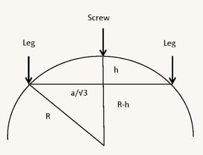
- Spherometer:
- Tool used to find the radii of a particular lens and is commonly used to measure the radius while grinding
- Basic setup consists of three legs and a micrometer (labeled screw in the drawing) to determine the depth
- Applied with trigonometry, one can quickly figure the sagitta (h) and then relate it to a curvature
- If any distance between the legs and center is "a" then Radius = a^2/6h + h/2

- Test Plate:
- Using a lens workpiece and a known surface test glass, an operator can place the two together
- This is paired with a light source above the workpiece (usually helium light), which will produce a fringe pattern for the operator to determine the specifications
- One downfall of this system is that it contacts the optics which can scratch the lens surface
- Another issue is that the technician is making a subjective call with the human eye
- This methodology is still used today for large radii or for items that cannot be seen with traditional interferometer due to travel issues


Works Citied:
“Chapter 2.4.” Optical Shop Testing, by Daniel Malacara, Wiley- Interscience, 2007, pp. 62–64.
“Fizeau Measurement of a Lens Surface.” Photon Engineering, photonengr.com/fred-software/application-examples/fizeau- measurement-of-a-lens-surface/.
Holloway, April. “Is the Assyrian Nimrud Lens the Oldest Telescope in the World?” Ancient Origins, Ancient Origins, 24 Feb. 2014, www.ancient-origins.net/ancient-technology/assyrian-nimrud- lens-oldest-telescope-world-001381.
“Wisdom Images.” Crystalgraphics Powerpictures, www.crystalgraphicsimages.com/search/wisdom-images.


